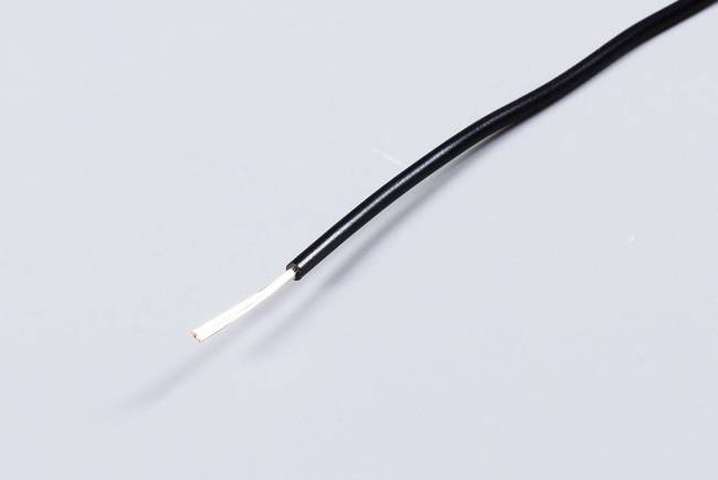
Do you really understand the UL1015 electronic wire?

As an internal connecting wire for electrical equipment, UL1015 electronic wire plays a crucial role in the internal circuit connections of various electrical devices. It ensures stable electrical connections between different components of the equipment and is an important basic component for guaranteeing the normal operation of electrical appliances.
Its temperature - resistance levels cover 80°C, 90°C, and 105°C, which can meet the temperature requirements of different usage environments and equipment. In terms of voltage, it supports 600Vac and 750Vdc, adapting to the voltage specifications of various electrical systems and providing a stable power - transmission channel for equipment.
It must pass the UL VW - 1 and CSA Ft1 vertical flame - resistance tests. This characteristic greatly improves the safety in use, effectively reducing the risk of fire in abnormal situations such as electrical failures, and providing reliable protection for the safety of electrical equipment and users.
It consists of two parts: an insulating layer and a conductor. The outer skin uses a PVC insulating layer. PVC, polyvinyl chloride, has good insulating and mechanical properties, effectively protecting the internal conductor. The internal conductor is divided into two types: bare copper and tinned copper. Different types of conductors have their own characteristics in terms of electrical conductivity, oxidation resistance, etc., to meet the needs of different application scenarios.
In addition to passing the UL VW - 1 and CSA Ft1 vertical flame - resistance tests, the thickness of the insulating layer needs to be uniform. A uniform insulating - layer thickness ensures that the insulating performance of the electronic wire is consistent everywhere during use, avoiding potential safety hazards such as electric leakage and short - circuits caused by uneven insulating - layer thickness, and guaranteeing the overall quality and stability of the electronic wire.
Generally suitable for fixed - laying scenarios, such as in conduit - installed lines and T - shaped fluorescent lamp fixtures. In these scenarios, single - strand bare - copper electronic wires are more convenient for making line connections and equipment wiring, with relatively simple operations. In contrast, multi - strand copper wires usually require more complex connection methods such as crimping or soldering in similar scenarios.
Due to the relatively soft texture of copper wires, multi - strand wires are suitable for occasions where the wires need to move, such as in motors, electrical cabinets, distribution boxes, instruments, chargers, audio systems, medical equipment, toys, and household appliances. At the same time, when multiple wires are laid together, multi - strand wires are more convenient for wire laying and wire - bundle formation. Compared with single - strand wires, they are more widely used in control circuits, better meeting the requirements of control circuits for wire flexibility and signal - transmission stability.
|
Model |
Conductor Specification |
Insulation Thickness (mm) |
Finished Outer Diameter (mm) |
Maximum Conductor Resistance (Ω/km, 20°C) |
Withstand Voltage Strength (VAC, 1min) |
|
AWG Specification |
Structure (No/mm) |
|
|
|
|
|
30 |
7/0.10 |
0.77 |
1.90 |
376.96 |
2000 |
|
28 |
7/0.127 |
0.77 |
2.00 |
237.25 |
2000 |
|
26 |
7/0.16 |
0.77 |
2.10 |
148.94 |
2000 |
|
24 |
11/0.16 |
0.77 |
2.2 |
93.25 |
2000 |
|
22 |
17/0.16 |
0.77 |
2.35 |
55.0 |
2000 |
|
UL1015 (Multi - strand) |
20 |
16/0.25 |
0.77 |
2.55 |
34.6 |
|
18 |
16/0.25 |
0.77 |
2.80 |
21.8 |
2000 |
|
16 |
26/0.25 |
0.77 |
3.15 |
13.7 |
2000 |
|
14 |
41/0.25 |
0.77 |
3.55 |
8.62 |
2000 |
|
12 |
65/0.25 |
0.77 |
4.05 |
5.43 |
2000 |
|
10 |
105/0.25 |
0.77 |
4.9 |
3.41 |
2000 |
|
8 |
168/0.25 |
0.77 |
6.60 |
2.23 |
2000 |
|
6 |
266/0.25 |
0.77 |
8.50 |
1.403 |
2000 |
|
4 |
420/0.25 |
0.77 |
9.80 |
0.882 |
2000 |
|
3 |
532/0.25 |
0.77 |
10.7 |
0.6996 |
2000 |
|
2 |
665/0.25 |
0.77 |
11.6 |
0.5548 |
2000 |
|
1 |
836/0.25 |
0.77 |
13.7 |
0.4398 |
2000 |
|
10 |
1045/0.25 |
0.77 |
14.8 |
0.3487 |
2000 |
|
20 |
1330/0.25 |
0.77 |
17.6 |
0.2766 |
2000 |
|
30 |
1672/0.25 |
0.77 |
17.6 |
0.2194 |
2000 |
|
Model |
Conductor Specification |
Insulation Thickness (mm) |
Finished Outer Diameter (mm) |
Maximum Conductor Resistance (Ω/km, 20°C) |
Withstand Voltage Strength (VAC, 1min) |
|
AWG Specification |
Structure (No/mm) |
|
|
|
|
|
UL1015 (Single - strand) |
26 |
1/0.404 |
0.77 |
2.10 |
148.94 |
|
24 |
1/0.511 |
0.77 |
2.2 |
93.25 |
2000 |
|
22 |
1/0.643 |
0.77 |
2.35 |
55.0 |
2000 |
|
20 |
1/0.813 |
0.77 |
2.55 |
34.6 |
2000 |
|
18 |
1/1.024 |
0.77 |
2.80 |
21.8 |
2000 |
|
16 |
1/1.29 |
0.77 |
3.15 |
13.7 |
2000 |
|
14 |
1/1.63 |
0.77 |
3.55 |
8.62 |
2000 |
|
12 |
1/2.050 |
0.77 |
4.05 |
5.43 |
2000 |
|
10 |
1/2.588 |
0.77 |
4.9 |
3.41 |
2000 |
Please Read On, Stay Posted, Subscribe, And We Welcome You To Tell Us What You Think.
Copyright @ 2025 ShenZhen Era WingShing Electronics Co.,Ltd. All Rights Reserved.  Network Supported